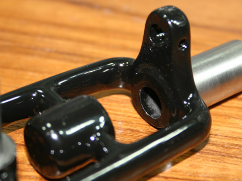
Bottom
view of the Friction
Roll mounting bracket.
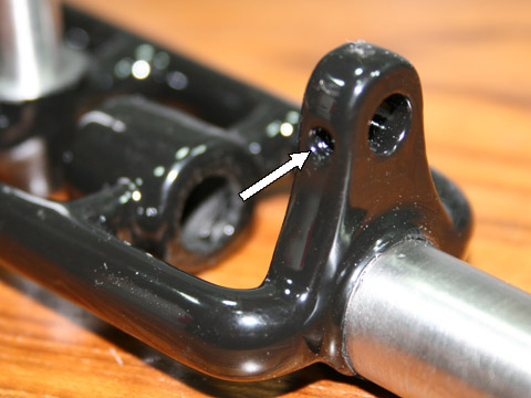
The same mounting
bracket from different view-point. The arrow points
to the place where locking screw will be place. The screw
will lock the shaft of the "Friction Roll" in the desired position.
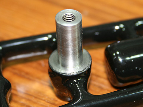
Here is the shaft for main
gear. It is an integral part of the frame casting and
machined to final shape. Polished surface will ensure smooth turning
of the gear. The tread in the center of the shaft is
provided for gear locking screw.
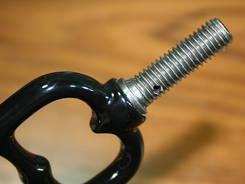
This is the handle mounting threaded rod. This rod is cast as an
integral part of the frame, the tenon for a handle ferrule is machined
and the thread is cut. As we will see on the next page,
this is an important detail.
One of continuing vulnerability of the No. 2
drill was the way main handle was attached to the frame.
This vulnerability manifested itself in cracks of the handle at
the point of attachment to the frame. It is especially
notorious on the drills introduced sometime after 1906 when
thicker handles were implemented, following changes in the frame
design. The new handle was much thicker at the point of
attachment to the frame and carried wider, stepped ferrule.
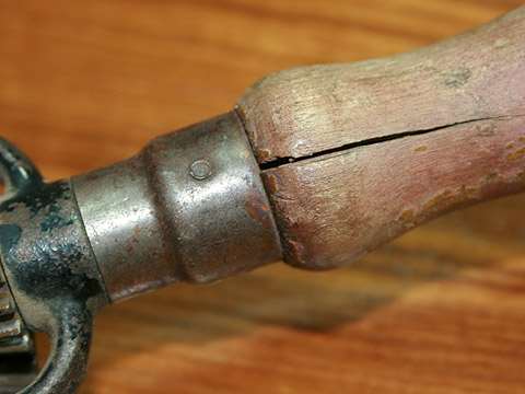
Here are some pictures showing the problem on
drill from c. 1938.
There are a variety of reasons for this persistent vulnerability and
they are analyzed in depth by George Langford in his No. 2 drill
type study. Spend some time on his web site at
GeorgesBasement.com - well worth it! In addition to
his finding, I believe there is one more reason for this
problem.