|
|
Construction Details
|
|
|
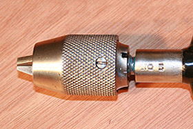
Chuck installed on Hand Drill No. 5. |
|
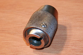
Chuck dismounted. |
|
|
|
|
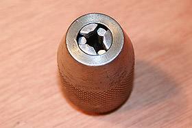
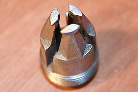
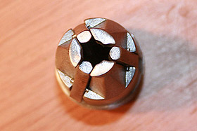
View from the top. |
|
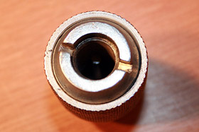
View from the bottom. |
|
|
|
|
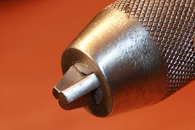 Chuck with jaws extended. |
|
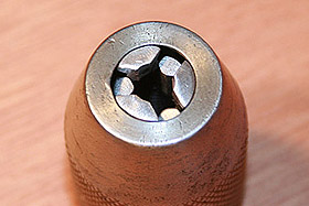 Top view with jaws
collapsed. |
|
|
|
|
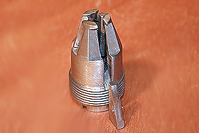
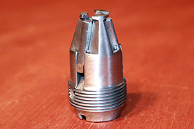
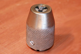 Side view with a
locking screw visible.
The purpose of this screw is to hold chuck's shell
attached to the base without risking removal of the
shell when base is tightly screwed on
the spindle. |
|
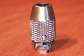
Side view with a locking screw removed and shell
unscrewed from the base. In order to separate
chuck's shell from base the locking screw has to be removed. |
|
|
|
|
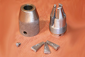 The chuck is built with six
parts:
-
Shell
-
Base
-
Blocking Screw
-
Three Jaws
|
|
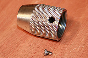
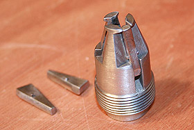
The shell and locking screw. |
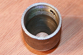
The shell - inside view. |
|
The base. |
|
|
|
|
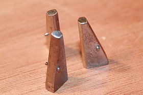
Three jaws. Each jaw has a pin that supports a jaw
on the ledge of a groove milled in the chuck's base.
|
|
One of the jaws placed in the groove.
The construction is very simple. The jaw slides
into the groove and is supported on ledge by a pin.
This pun provides means for a jaw to move freely up and
down and in and out of the groove. |
|
|
|
|
Another view - two jaws placed in the grooves and one
more positioned for placement. |
|
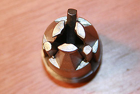 Jaws placed in their respective grooves and
positioned outward.
|
|
|
|
|
Jaws positioned inward in their grooves. |
|
Another view.
|
|